Maintenance
- The Required Maintenance Schedule specifies how often you should have your motorcycle serviced, and what things need attention. It is essential that your motorcycle be serviced as scheduled to retain its high level of safety, dependability, and emission control performance.
- These instructions are based on the assumption that the motorcycle will be used exclusively for its designed purpose. Sustained high speed operation or operation in unusually wet or dusty conditions will require more frequent service than specified in the MAINTENANCE SCHEDULE. Consult your authorized Honda dealer for recommendations applicable to your individual needs and use.
MAINTENANCE SCHEDULE
perform the Pre-ride Inspection (page 47) at each scheduled maintenance period.
	I : INSPECT AND CLEAN, ADJUST, LUBRICATE OR REPLACE IF NECESSARY
	C : CLEAN
	R : REPLACE
	A : ADJUST
	L : LUBRICATE
The following Maintenance Schedule specifies all maintenance required to keep your motorcycle in peak operating condition. Maintenance work should be performed in accordance with standards and specifications of Honda by properly trained and equipped technicians. Your authorized Honda dealer meets all of these requirements.
| FREQUENCY \ ITEM | WHICHEVER | ODOMETER READING (NOTE 1) | |||||||||
| COMES FIRST | x1,000 km | 1 | 6 | 12 | 18 | 24 | 30 | 36 | Refer to page | ||
| x1,000 mi | 0.6 | 4 | 8 | 12 | 16 | 20 | 24 | ||||
| NOTE | MONTHS | 6 | 12 | 18 | 24 | 30 | 36 | ||||
| * | FUEL LINE | I | I | I | - | ||||||
| * | THROTTLE OPERATION | I | I | I | - | ||||||
| * | CARBURETOR CHOKE | I | I | I | - | ||||||
| AIR CLEANER | NOTE 2 | R | R | 78 | |||||||
| SPARK PLUGS | I | R | I | R | I | R | 80 | ||||
| * | VALVE CLEARANCE | I | - | ||||||||
| ENGINE OIL | R | R | R | R | 75 | ||||||
| ENGINE OIL FILTER | R | R | R | R | 75 | ||||||
| * | CARBURETOR SYNCHRONIZATION | I | I | I | - | ||||||
| * | ENGINE IDLE SPEED | I | I | I | I | I | I | - | |||
| RADIATOR COOLANT | NOTE 3 | I | R | 22 | |||||||
| * | C00LING SYSTEM | I | I | - | |||||||
| * | SECONDARY AIR SUPPLY SYSTEM | NOTE 4 | I | I | - | ||||||
| ** | TIMING BELT | I: EVERY 100.000 km (60.000 mi) R: EVERY 150.000 km (90.000 mi) |
- | ||||||||
| FINAL DRIVE OIL | R | 29, 83 | |||||||||
| BRAKE FLUID | NOTE 3 | I | I | R | I | 1 | R | 18 | |||
| BRAKE PAD WEAR | I | I | I | I | I | I | 93 | ||||
| BRAKE SYSTEM | I | I | I | I | 18, 94 | ||||||
| * | BRAKE LIGHT SWITCH | I | I | I | - | ||||||
| * | HEADLIGHT AIM | I | I | I | - | ||||||
| CLUTCH SYSTEM | I | I | I | 21 | |||||||
| CLUTCH FLUID | NOTE 3 | I | I | R | I | I | R | 21 | |||
| SIDE STAND | I | I | I | 95 | |||||||
| * | SUSPENSION | I | I | I | - | ||||||
| * | NUTS, BOLTS, FASTENERS | I | I | I | I | - | |||||
| ** | WHEELS/TYRES | I | I | I | - | ||||||
| ** | STEERING HEAD BEARINGS | I | I | I | I | - | |||||
| * | SHOULD BE SERVICED BY AN AUTHORIZED HONDA DEALER, UNLESS THE OWNER HAS PROPER TOOL AND SERVICE DATA AND IS MECHANICALLY QUALIFIED. REFER TO THE OFFICIAL HONDA SHOP MANUAL |
| ** | IN THE INTEREST OF SAFETY, WE RECOMMEND THESE ITEMS BE SERVICED ONLY BY AN AUTHORISED HONDA DEALER. |
Honda recommends that your authorized Honda dealer should road test your motorcycle after each periodic maintenance is carried out
NOTES:
- At higher odometer readings, repeat at the frequency interval established here.
- Service more frequently when riding in unusually wet or dusty areas.
- Replace every 2 years, or at indicated odometer interval, whichever comes first. Replacement requires mechanical skill.
- Switzerland type only.
TOOL KIT
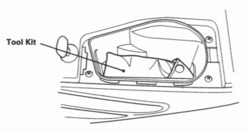
The tool kit is in the right fairing pocket. Open the right fairing pocket (page 43). Some roadside repairs, minor adjustments and parts replacement can be performed with the tools contained in the kit.
- Spark plug wrench
- 10 x 12 mm Box end wrench
- 14 mm Box end wrench
- 24 mm Box end wrench
- 27 mm Box end wrench
- 8 mm Open end wrench
- 10 x 12 mm Open end wrench
- 14 x 17 mm Open end wrench
- Pliers
- Screwdriver handle
- Screwdriver
- Pin spanner
- Pin spanner grip
- 5 mm Hex wrench
- 6 mm Hex wrench
- Feeler gauge 0.5 mm (Model equipped with CBS/ABS/TCS)
- Tool bag
SERIAL NUMBERS
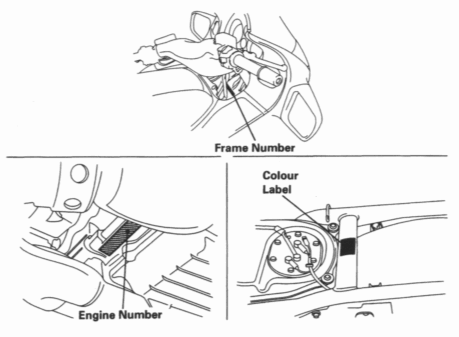
The frame and engine serial numbers are required when registering your motorcycle. They may also be required by your dealer when ordering replacement parts. Record the numbers here for your reference. The frame number is stamped on the right side of the steering head. The engine number is stamped on the rear of the lower crankcase behind the oil pan.
COLOUR LABEL
The colour label is attached to the frame under the seat. It helpful when ordering replacement parts. Record the colour and code here for your reference.
	FRAME NO _______________________________________
	ENGINE NO ______________________________________
	COLOUR _________________________________________
	CODE ___________________________________________
MAINTENANCE PRECAUTIONS
- If your motorcycle is overturned or involved in a collision, inspect control levers, cables, brake hoses, calipers, accessories, and other vital parts for damage. Do not ride the motorcycle if damage impairs safe operation. Have your authorized Honda dealer inspect the major components, including frame, suspension and steering parts, for misalignment and damage that you may not be able to detect.
- Stop the engine and support the motorcycle securely on a firm, level surface before performing any maintenance.
- Use new, genuine Honda parts or their equivalent for maintenance and repair. Parts which are not of equivalent quality may impair the safety of your motorcycle and the effective operation of the emission control systems.
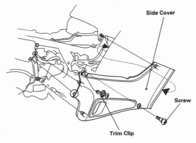
COVER REMOVAL
(Right side shown; left side similar)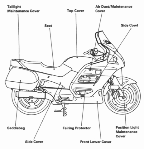
Side Cover
- Remove the saddlebag (see page 42)
- Remove the seat (see page 37)
- Remove the screw and trim clip. Pull the rear of the cover first, then rotate it clockwise and pull the front of the cover.
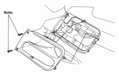
Air Duct/Maintenance Cover
- Remove the bolts, pull the cover out, then slide it to the rear.
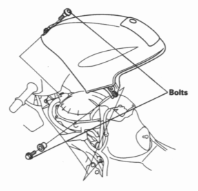
Top Cover
- Remove the seat (see page 37).
- Remove the top cover by removing bolts.
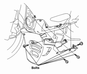
Front Lower Cover
- Remove the bolts, then slide the cover forward.
NOTE:
- Use the short collar bolt in the right rear hole when installing the front lower cover.
Position Light Maintenance Cover
- Remove the screws, then slide the cover to the rear.
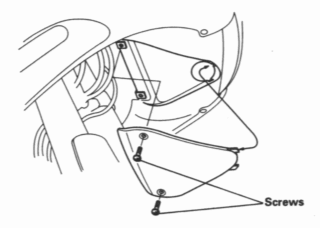
Taillight Maintenance Cover
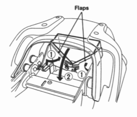
- Push the flaps of the document compartment in and back against the sides of the document compartment (1). Pull the rear of the document compartment up toward the front (2).
Side Cowl
- Remove the airduct/maintenance cover, top cover and front lower cover.
- Remove the right fairing pocket lid (page 43).
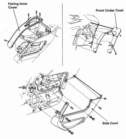
- Remove the fairing inner cover by removing the bolts and screws.
- Remove the front under cowl by removing the bolts and screws.
- Remove the side cowl by removing bolts and screws.
